
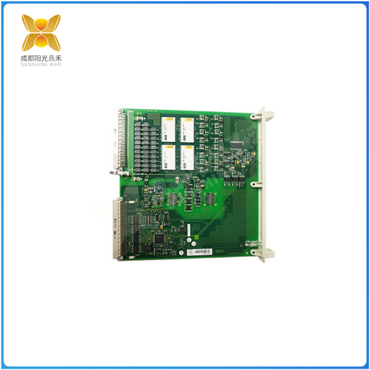
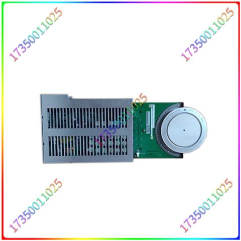
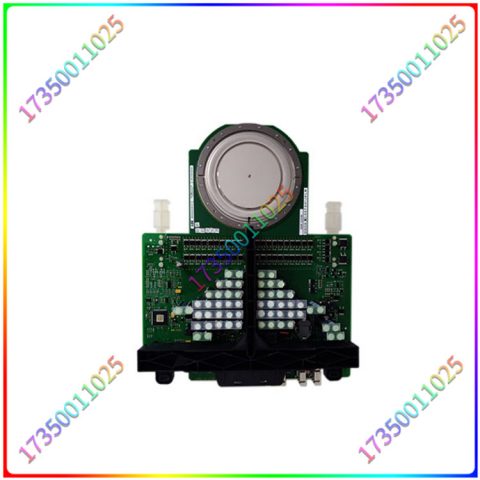
DSAI130A输人输出是PLC与外部设备进行信息交流的通道,其是否正常工作,除了和输入输出单元有关外,还与联接配线、接线端子、保险丝等元件状态有关。出现输入故障时,首先检查LED电源指示器是否响应现场元件(如按钮、行程开关等)。如果输入器件被激励(即现场元件已动作),而指示器不亮,则下一步就应检查输入端子的端电压是否达到正确的电压值。若电压值正确,则可替换输入模块。若一个LED逻辑指示器变暗,而且根据编程器件监视器、处理器未识别输入,则输入模块可能存在故障。如果替换的模块并未解决问题且连接正确,则可能是I/O机架或通信电缆出了问题。出现输出故障时,首先应察看输出设备是否响应LED状态指示器。若输出触点通电,模块指示器变亮,输出设备不响应。

DSAI130A
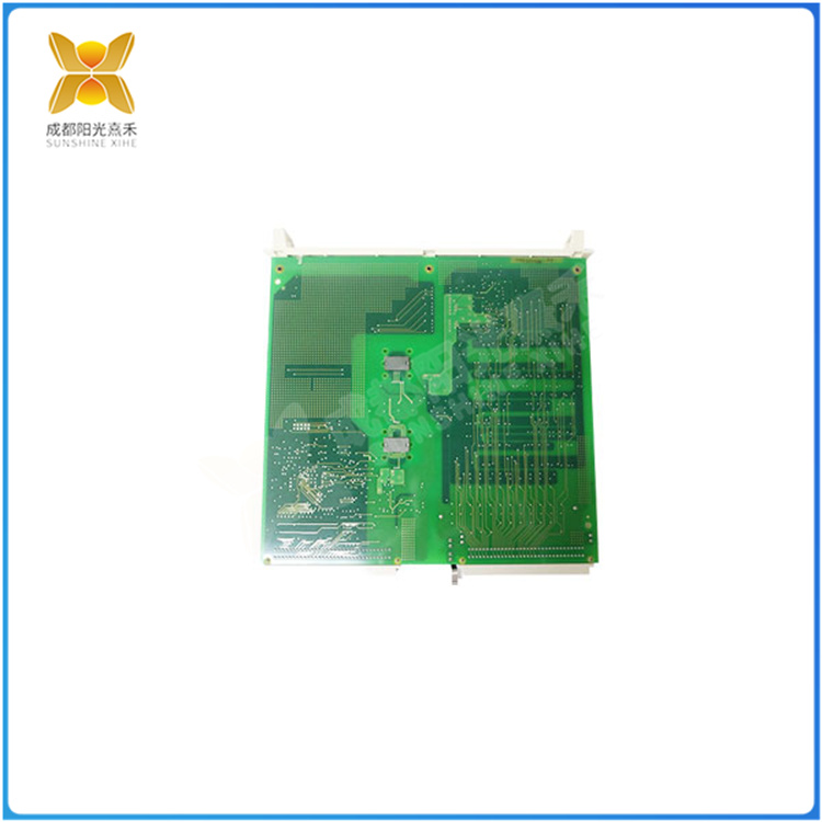
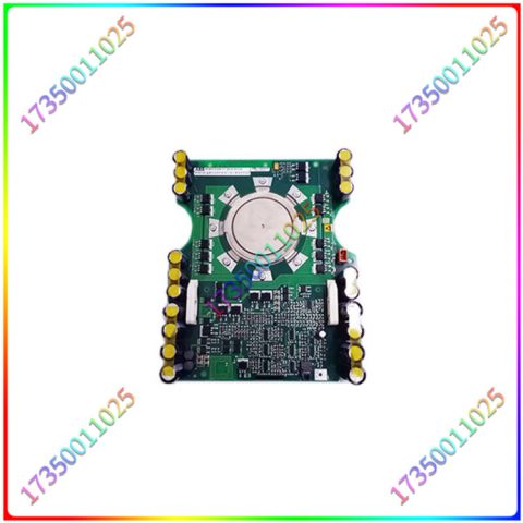
那么,首先应检查保险丝或替换模块。若保险丝完好,替换的模块未能解决问题,则应检查现场接线。若根据编程设备监视器显示一个输出器被命令接通,但指示器关闭,则应替换模块。在诊断输入/输出故障时,最佳方法是区分究竟是模块自身的问题,还是现场连接上的问题。如果有电源指示器和逻辑指示器,模块故障易于发现。通常,先是更换模块,或测量输入或输出端子板两端电压测量值正确,模块不响应,则应更换模块。若更换后仍无效,则可能是现场连接出问题了。输出设备截止,输出端间电压达到某一预定值,就表明现场连线有误。若输出器受激励,且LED指示器不亮,则应替换模块。如果不能从I/O模块中查出问题,则应检查模块接插件是否接触不良或未对准。最后,检查接插件端子有无断线,模块端子上有无虚焊点。

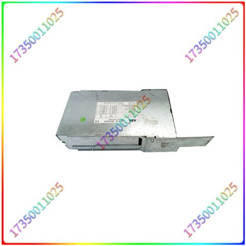
DSAI130A
DSAI130A input and output is a channel for communication between PLC and external devices. Its normal operation is not only related to the input and output units, but also to the status of connecting wiring, wiring terminals, fuses and other components. When an input fault occurs, first check whether the LED power indicator responds to on-site components (such as buttons, travel switches, etc.). If the input device is excited (i.e. the field component has been activated) and the indicator does not light up, the next step is to check whether the terminal voltage of the input terminal has reached the correct voltage value. If the voltage value is correct, the input module can be replaced. If an LED logic indicator becomes dim and the input is not recognized by the programmer’s monitor or processor, there may be a fault in the input module. If the replacement module does not solve the problem and is connected correctly, it may be a problem with the I/O rack or communication cable. When an output fault occurs, the first thing to check is whether the output device responds to the LED status indicator. If the output touchpoint is powered on, the module indicator will light up and the output device will not respond.
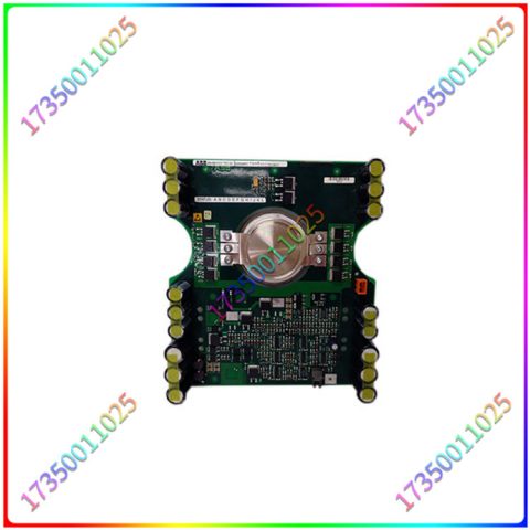
DSAI130A
So, first check the fuse or replace the module. If the fuse is intact and the replacement module fails to solve the problem, the on-site wiring should be checked. If according to the programming device monitor, an output is commanded on but the indicator is turned off, the module should be replaced. The best way to diagnose input/output faults is to distinguish whether it is a problem with the module itself or a problem with the on-site connection. If there are power indicators and logic indicators, module faults are easy to detect. Usually, the first step is to replace the module, or if the voltage measurement at both ends of the input or output terminal board is correct and the module does not respond, the module should be replaced. If the replacement is still ineffective, it may be a problem with the on-site connection. When the output device is cut off and the voltage between the output terminals reaches a predetermined value, it indicates that there is an error in the on-site wiring. If the output is excited and the LED indicator is not on, the module should be replaced. If the problem cannot be detected from the I/O module, the module connectors should be checked for poor contact or misalignment. Finally, check if there are any broken wires on the connector terminals and if there are any virtual solder joints on the module terminals.
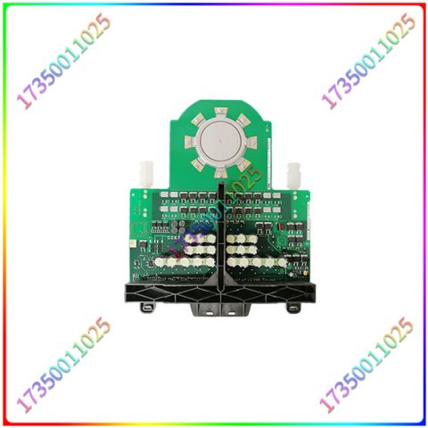
DSAI130A

There are no reviews yet.