

ABB REF541KM118AAAA如果光栅或捕捉处于活动状态,对象只能放置在固定位置;因此,可以更好地对对象对齐。冗余连接用于同步冗余数据的两个冗余合作伙伴的物理连接。冗余链路通过冗余链路,执行冗余合作伙伴主节点和辅助节点的同步。冗余同步冗余控制器之间的第一次同步并行运行于“”加载整个站点”或”加载更改的对象””。首先将操作系统加载到辅助程序中,然后是用户程序,最后是当前进程数据。一旦成功地实现了第一次同步,两个冗余站都传递到状态同步。从现在开始,数据将在两个控制器之间进行周期性的调整。冗余切换当活动控制器(主节点)检测到问题或切换已被主动触发时,例如通过操作员操作,会发生冗余切换。
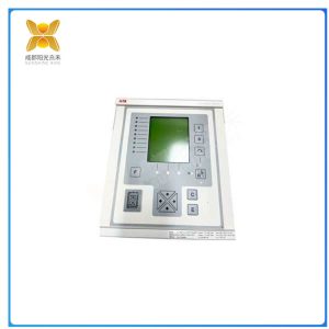
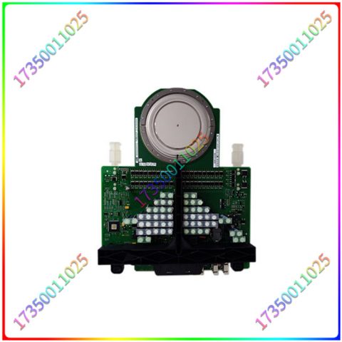
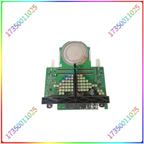
REF541KM118AAAA

REF541KM118AAAA
馈线保护测控装置的作用馈线保护测控装置是电力系统中的一个重要保护设备,主要作用是在馈线发生短路、接地故障或其他异常情况时,快速切除故障,保护电力系统的稳定运行。它可以感应电力系统中的异常电流、电压信号,与事先设定的故障保护条件进行比较,当检测到故障时实现快速切断故障环节,防止故障向电网扩散。馈线保护测控装置的原理馈线保护测控装置的工作原理是基于安设在馈线上的电流、电压传感器,通过对故障信号的检测、测量、处理,进行故障的判断和快速切除。它采用数字信号处理技术,可以快速、准确地检测馈线故障,实现快速切除故障,保障电力系统的稳定运行。
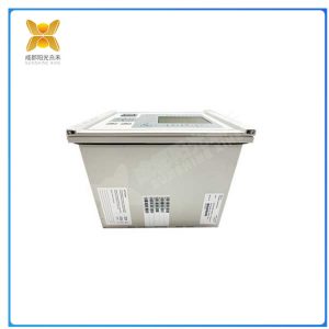
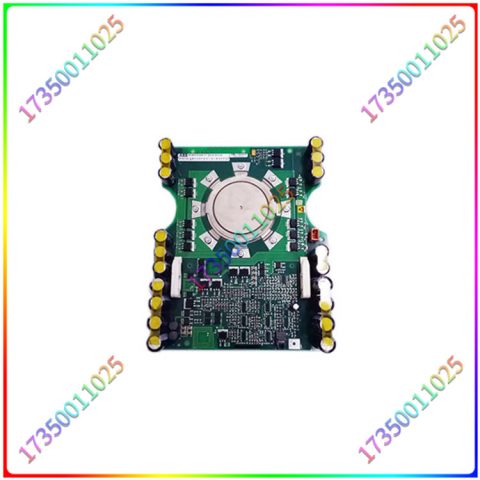
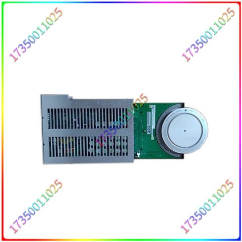
REF541KM118AAAA
、ABB REF541KM118AAAA If the raster or snap is active, the object can only be placed in a fixed position; Therefore, it is possible to better align objects. Redundant connections are physical connections between two redundant partners used to synchronize redundant data. Redundant links perform synchronization between the primary and secondary nodes of redundant partners through redundant links. The first synchronization between redundant controllers runs in parallel with “loading the entire site” or “loading changed objects”. First, load the operating system into the auxiliary program, then the user program, and finally the current process data. Once the first synchronization is successfully achieved, both redundant stations are transmitted to state synchronization. From now on, the data will be periodically adjusted between the two controllers. Redundant switching occurs when the active controller (master node) detects a problem or the switch has been actively triggered, such as through operator operation.

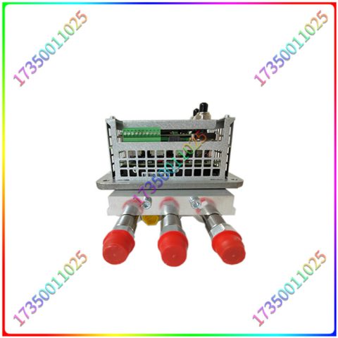
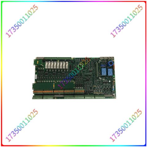
REF541KM118AAAA
The structure of intelligent feeder terminal: Intelligent feeder terminal generally consists of control part, data processing part, communication part, and power supply part. Control part: Energy storage, closing operation, and opening operation of circuit breakers. Data processing: Integrated FTU, relying on FTU to complete data collection and processing. Communication part: integrated communication module, 4G wireless communication, fiber optic communication, etc. Power supply: Built in battery or supercapacitor, power supply includes AC/DC220, DC48.DC24, etc. The previous auxiliary node is the new main node and takes over the further execution of the program
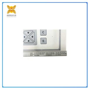
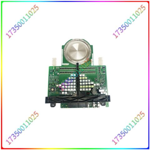
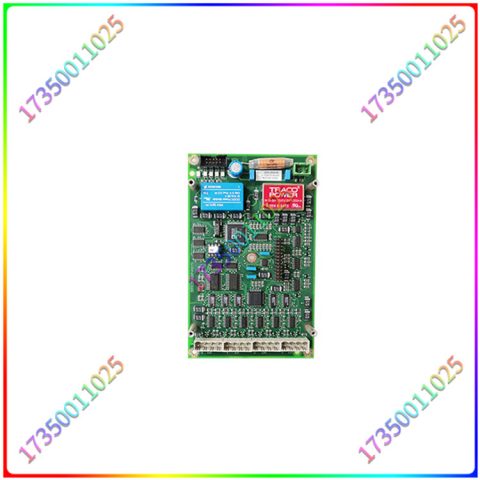
REF541KM118AAAA
The function of the feeder protection measurement and control device is an important protective device in the power system. Its main function is to quickly remove faults and protect the stable operation of the power system in the event of a short circuit, grounding fault, or other abnormal situation in the feeder. It can sense abnormal current and voltage signals in the power system, compare them with pre-set fault protection conditions, and quickly cut off the fault link when a fault is detected, preventing the fault from spreading to the power grid. The working principle of the feeder protection measurement and control device is based on the current and voltage sensors installed on the feeder, which detect, measure, and process fault signals to determine and quickly remove faults. It adopts digital signal processing technology, which can quickly and accurately detect feeder faults, achieve rapid fault removal, and ensure the stable operation of the power system
There are no reviews yet.