特点:灵活使用各种操作模式精确位置控制扩展输入和输出提高了速度控制性能谐波驱动系统SC-500和SC-510系列伺服控制器已设计用于驱动RS和FHA系列交流伺服执行器。有三个基本单元,标称电流分别为2.5A、5A和7.5A。数字控制原理和16位反馈操作即使在非常低的速度下也能实现非常平稳的速度行为。通过设置软件提供的各种可调操作模式可实现与典型CNC、PLC和步进电机控制器相关的各种不同应用。此外,SC-510系列能够使用通过PC的RS-232或RS-422接口在线发送的ASCII序列进行单轴或多轴控制
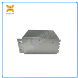
SC-510-5-230-S0
伺服电机,按控制命令的要求、对功率进行放大、变换与调控等处理,使驱动装置输出的力矩、速度和位置控制的非常灵活方便。由于它的“伺服”性能,因此它就被命名为伺服电机。其功能是将输入的电压控制信号转为轴上输出的角位移和角速度驱动控制对象。伺服电机一般分为两大类:直流伺服电机、交流伺服电机。交流伺服电机内部的转子是永磁铁,驱动器控制的U/V/W三相电形成电磁场,转子在此磁场的作用下转动,同时电机自带的编码器反馈信号给驱动器,驱动器根据反馈值与目标值进行比较,调整转子转动的角度。交流伺服电机在没有控制电压时,定子内只有励磁绕组产生的脉动磁场,转子静止不动。当有控制电压时,定子内便产生一个旋转磁场,转子沿旋转磁场的方向旋转,在负载恒定的情况下,电动机的转速随控制电压的大小而变化,当控制电压的相位相反时,伺服电动机将反转。
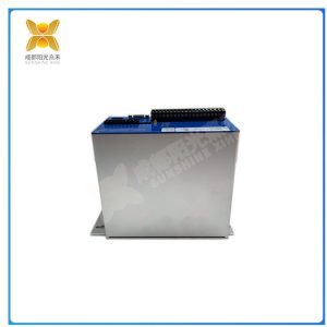
SC-510-5-230-S0
伺服驱动器又称为伺服放大器或放大器,是将从控制入的脉冲信号或模拟量信号经内部计算放大后输出给电机的装置。结构及原理伺服驱动器主要有伺服控制单元、功率驱动单元、通讯接口单元组成。其中伺服控制单元包括位置控制器、速度控制器、转矩和电流控制器等。伺服驱动器大体可以划分为功能比较独立的功率板和控制板两个模块。功率板是强电部分,其中包括两个单元,一是功率驱动单元IPM用于电机的驱动,二是开关电源单元为整个系统提供数字和模拟电源。控制板是弱电部分,是电机的控制核心也是伺服驱动器技术核心控制算法的运行载体。控制板通过相应的算法输出PWM/PFM信号,作为驱动电路的驱动信号,来改变逆变器的输出功率,以达到控制交流伺服电机的目的。
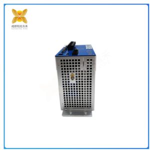
SC-510-5-230-S0
Features: Flexible use of various operating modes, precise position control, extended input and output, improved speed control performance, harmonic drive system SC-500 and SC-510 series servo controllers have been designed to drive RS and FHA series AC servo actuators. There are three basic units with nominal currents of 2.5A, 5A, and 7.5A, respectively. The principle of digital control and 16 bit feedback operation can achieve very smooth speed behavior even at very low speeds. By setting various adjustable operation modes provided by the software, various applications related to typical CNC, PLC, and stepper motor controllers can be achieved. In addition, the SC-510 series can use ASCII sequences sent online through the RS-232 or RS-422 interface of a PC for single axis or multi axis control.
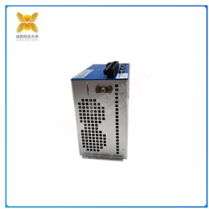
SC-510-5-230-S0
The servo motor amplifies, transforms, and regulates the power according to the requirements of control commands, making the torque, speed, and position control output by the driving device very flexible and convenient. Due to its “servo” performance, it is named a servo motor. Its function is to convert the input voltage control signal into angular displacement and angular velocity output on the shaft to drive the control object. Servo motors are generally divided into two categories: DC servo motors and AC servo motors. The rotor inside the AC servo motor is a permanent magnet, and the U/V/W three-phase electricity controlled by the driver forms an electromagnetic field. The rotor rotates under the action of this magnetic field. At the same time, the motor’s built-in encoder provides feedback signals to the driver, and the driver compares the feedback value with the target value to adjust the rotation angle of the rotor. When there is no control voltage in the AC servo motor, only the pulsating magnetic field generated by the excitation winding in the stator, and the rotor remains stationary. When there is a control voltage, a rotating magnetic field is generated in the stator, and the rotor rotates in the direction of the rotating magnetic field. Under constant load, the speed of the motor changes with the magnitude of the control voltage. When the phase of the control voltage is opposite, the servo motor will reverse
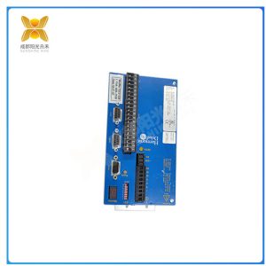
SC-510-5-230-S0
Servo driver, also known as servo amplifier or amplifier, is a device that outputs the pulse signal or analog signal input from the controller to the motor after internal calculation and amplification. The structure and principle of servo drivers mainly consist of servo control units, power drive units, and communication interface units. The servo control unit includes position controller, speed controller, torque and current controller, etc. The servo driver can generally be divided into two modules: a power board and a control board, which are functionally independent. The power board is a strong current part, which includes two units. One is the power drive unit IPM used for motor drive, and the other is the switching power supply unit that provides digital and analog power for the entire system. The control board is the weak current part, which is the control core of the motor and the operating carrier of the servo driver technology core control algorithm. The control board outputs PWM/PFM signals through corresponding algorithms as the driving signal of the driving circuit to change the output power of the inverter, in order to achieve the purpose of controlling the AC servo motor

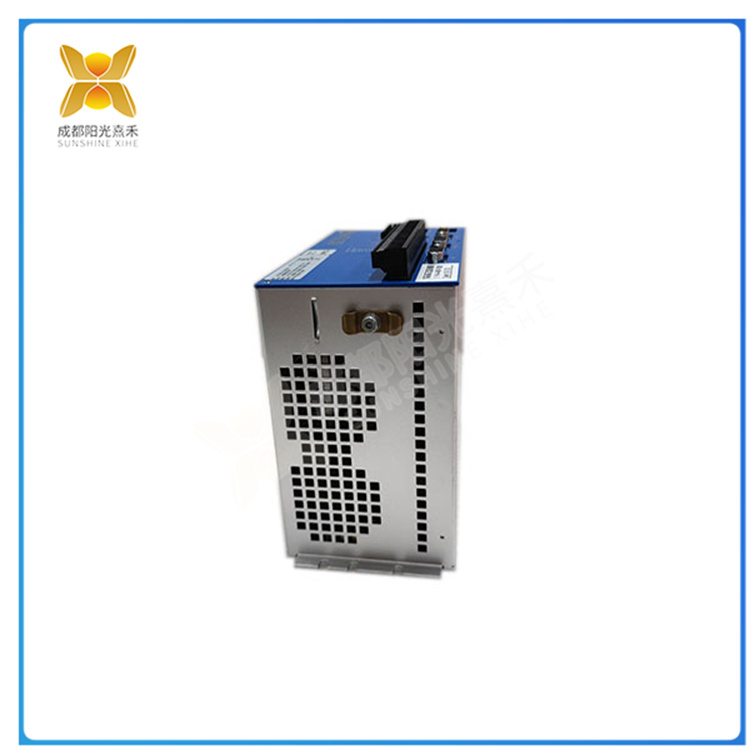
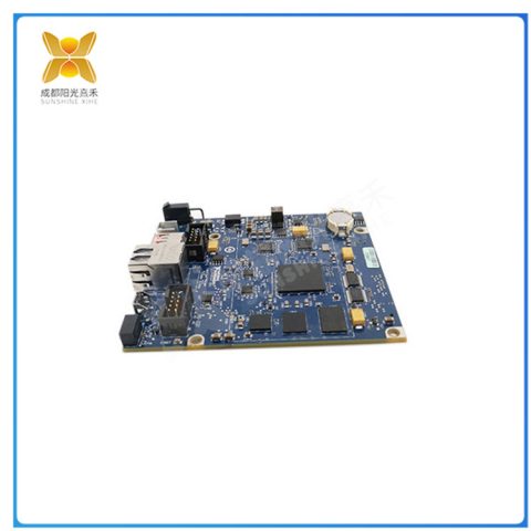
There are no reviews yet.