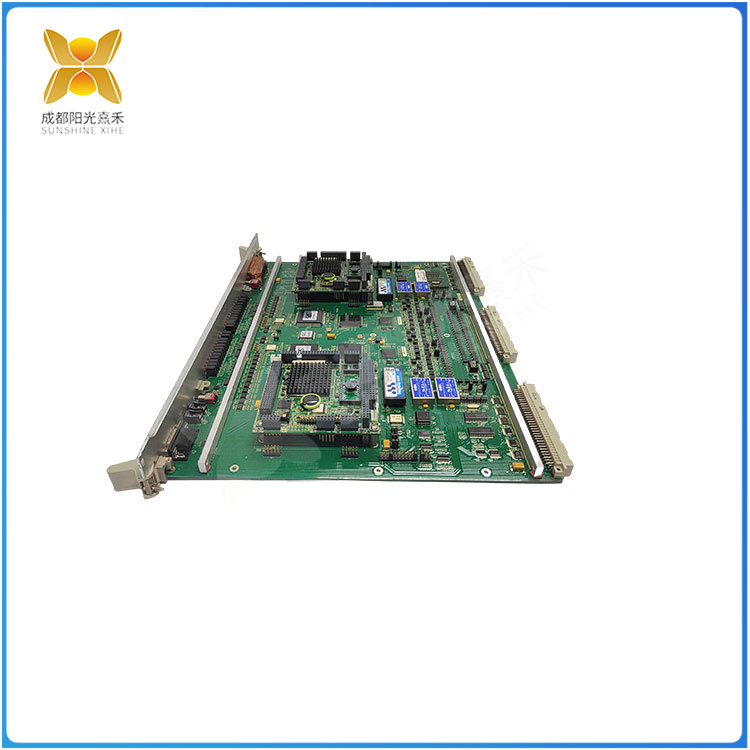
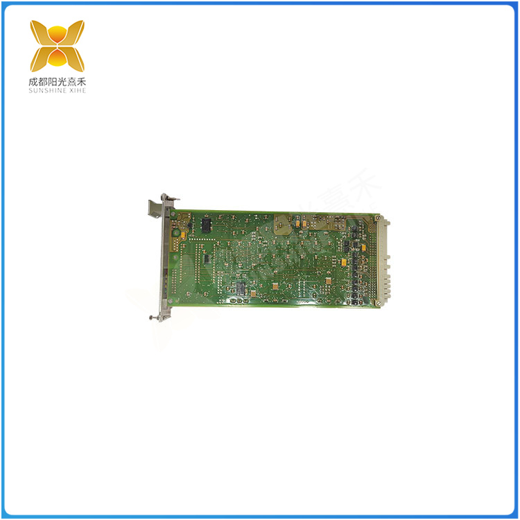
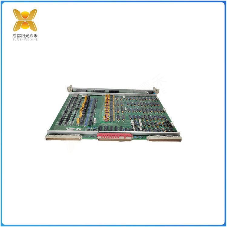
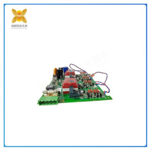
带程序的芯片wifi显微镜进行电路板检测1.EPROM芯片一般不宜损坏. 因这种芯片需要紫外光才能擦除掉程序,故在测试中不会损坏程序.但有资料介绍:因制作芯片的材料所致,随着时间的推移(年头长了),即便不用也有可能损坏(主要指程序).所以要尽可能给以备份.2.EPROM,SPROM等以及带电池的RAM芯片,均极易破坏程序.这类芯片否在使用<测试仪>进行VI曲线扫描后,是否就破坏了程序,还未有定论尽管如此,同仁们在遇到这种情况时,还是小心为妙笔者曾经做过多次试验,可能大的原因是:检修工具(如测试仪,电烙铁等)的外壳漏电所致.3.对于电路板上带有电池的芯片不要轻易将其从板上拆下来.二复位电路,待修电路板上有大规模集成电路时,应注意复位问题.在测试前最好装回设备上,反复开,关机器试-试以及多按几次复位键三功能与参数测试便携显微镜进行电路板检测<测试仪>对器件的检测,仅能反应出截止区,放大区和饱和区但不能测出工作频率的高低和速度的快慢等具体数值等。
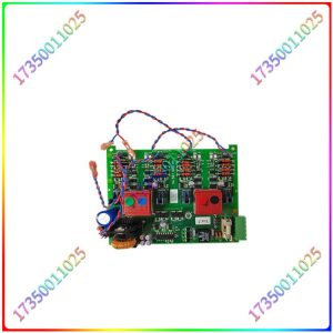
V4561983-0100
同理对TTL数字芯片而言,也只能知道有高低电平的输出变化.而无法查出它的上升与下降沿的速度.四.晶体振荡器1.通常只能用示波器(晶振需加电)或频率计测试,万用表等无法测量否则只能采用代换法了.2.晶振常见故障有:a.内部漏电,b.内部开路C.变质频偏d.外围相连电容漏电,这里漏电现象,用<测试仪>的VI曲线应能测出.3.整板测试时可采用两种判断方法:a.测试时晶振附近既周围的有关芯不通过.b.除晶振外没找到其它故障点便携式显微镜检测电路板4.晶振常见有2种a.两脚.b.四脚,其中第2脚是加电源的,注意不可随意短路.五.故障现象的分布1.电路板故障部位的不完全统计:1)芯片损坏30%, 2)分立元件损坏30%, 3)连线(PCB板敷铜线)断裂30%, 4)程序破坏或丢失10%(有上升趋势).2.由上可知,当待修电路板出现联线和程序有问题时,又没有好板子既不熟悉它的连线,找不到原程序此板修好的可能性就不大了。
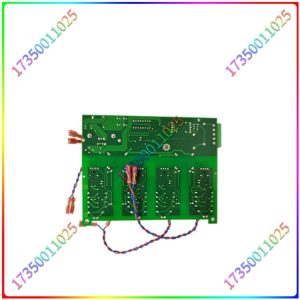
V4561983-0100
Using a WiFi microscope with a program for circuit board testing. 1. EPROM chips are generally not suitable for damage. This type of chip requires ultraviolet light to erase the program, so it will not damage the program during testing. However, there is information that due to the materials used to make the chip, over time (over time), even if not used, it may be damaged (mainly referring to the program). Therefore, it is necessary to provide backup as much as possible. 2. EPROM, SPROM, and RAM chips with batteries, It is highly susceptible to program damage. It is not yet certain whether this type of chip will break the program after using the<tester>to scan the VI curve. However, when encountering this situation, colleagues are still careful. The clever writer has conducted multiple experiments, which may be due to leakage from the casing of repair tools (such as testers, soldering irons, etc.). 3. For chips with batteries on the circuit board, do not easily remove them from the board. 2. Reset the circuit, When there is a large-scale integrated circuit on the circuit board to be repaired, attention should be paid to the reset issue. Before testing, it is best to reinstall the device, repeatedly turn on, turn off the machine for testing, and press the reset button multiple times. The portable microscope performs circuit board testing and parameter testing. The tester can only reflect the cutoff area, amplification area, and saturation area, but cannot measure specific values such as the high and low operating frequency and speed.
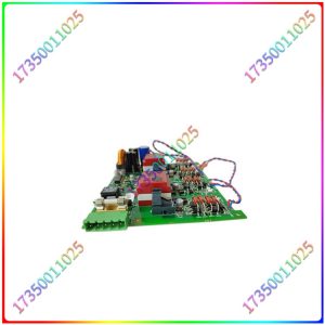
V4561983-0100
Similarly, for TTL digital chips, only high and low level output changes can be known, and the speed of its rising and falling edges cannot be detected. 4. Crystal oscillators. 1. Usually, they can only be tested with an oscilloscope (the crystal oscillator needs to be powered on) or a frequency meter, and cannot be measured with a multimeter. Otherwise, substitution methods can only be used. 2. Common faults of crystal oscillators include: a. internal leakage, b. internal open circuit, C. deterioration frequency deviation, d. peripheral connected capacitor leakage, where leakage occurs, The VI curve of the<tester>should be able to be measured. 3. Two judgment methods can be used during the entire board test: a. The relevant cores near the crystal oscillator do not pass during the test. b. No other fault points were found except for the crystal oscillator. The portable microscope detects the circuit board. 4. There are two common types of crystal oscillators: a. Two pins. b. Four pins, of which the second pin is powered on, and attention should not be paid to random short circuits. 5. Distribution of fault phenomena. 1. Incomplete statistics of the faulty parts of the circuit board: 1) 30% of chip damage, 2) Discrete components are damaged by 30%, 3) wiring (PCB board copper wire) is broken by 30%, 4) program is damaged or lost by 10% (with an upward trend). 2. As can be seen from the above, when there are problems with wiring and program on the circuit board to be repaired, and there is no good board that is not familiar with its wiring, the possibility of not finding the original program and repairing this board is low.
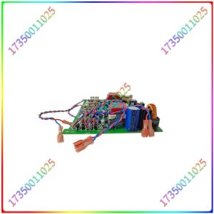
V4561983-0100

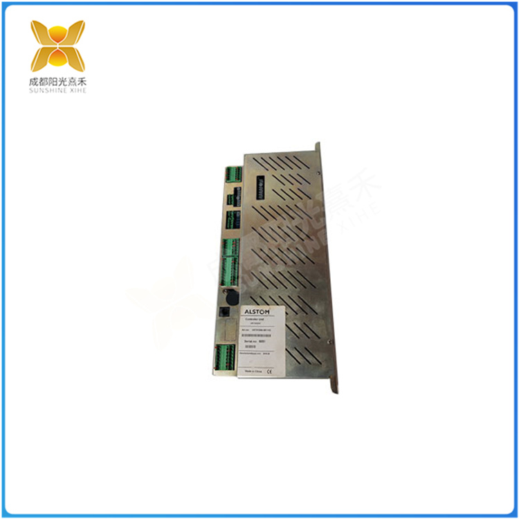
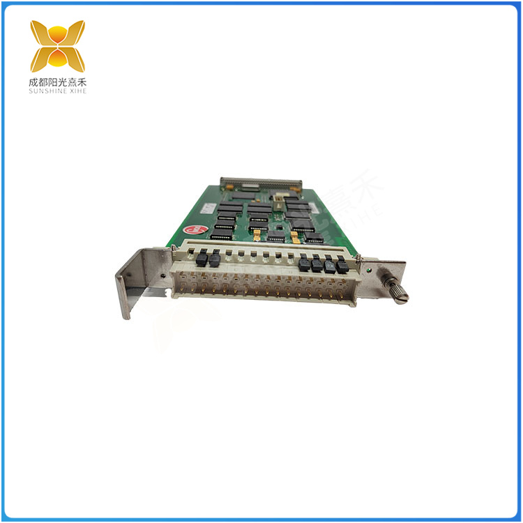
There are no reviews yet.