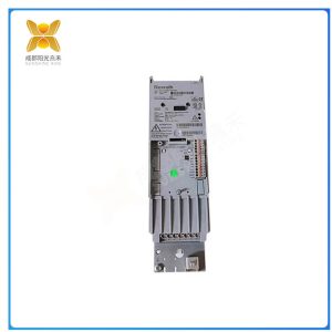
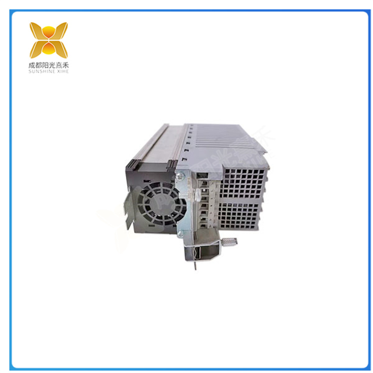
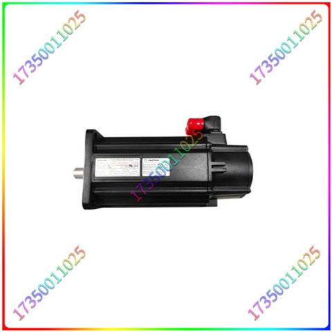
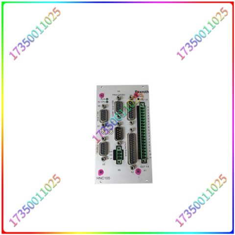
高性能伺服控制: 该驱动模块设计用于控制伺服电机,提供高性能的运动控制,包括精确定位、速度控制和扭矩控制。多种输入输出接口: 通常具备多种输入输出接口,以便连接到不同类型的传感器、编码器和其他控制设备。多轴控制: 该模块通常支持多轴控制,允许同时控制多个伺服电机,适用于多轴运动应用。高分辨率编码器反馈: 通常支持高分辨率编码器,以提供高精度的位置反馈。开放式通信协议支持: 通常支持多种开放式通信协议,如EtherCAT、CANopen等,以便于与其他控制系统进行通信和集成。参数可调性: 用户通常可以根据具体应用的需求调整和配置参数,以实现不同的运动控制模式。紧凑设计: 通常具有紧凑的物理尺寸,适合安装在有限空间内。高效能节能: 常采用先进的功率电子技术,以提高效率和降低能耗。
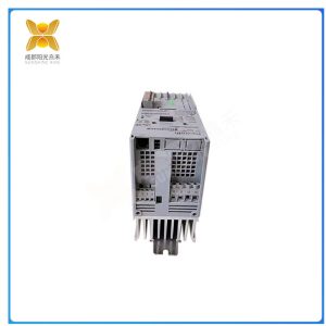
R911311065
输出电路在系统运行过程中主要是通过变频器或指示灯等设备向外部发出信号。对于输出电路的设计,应该要从整个电路的安全性出发。在输出电路的设计过程中,一定要按照PLC自动化控制系统的要求进行设计,应该利用晶体管提高系统运行效率。在运行效率比较低的工作环境中,可以选择使用续电设备,将其作为输出电路设备。这个工作流程就比较简单,而且相应的工作效率也很高,可以在很大程度上增强PLC自动化控制系统输出电路的负载能力。如果PLC输出带一些感性负载的话,负载在断电的情况下会对PLC的输出造成浪涌电流冲击,可以采用在直流感性负载旁边并接绫流二极管,交流感性负载并接浪涌的措施来将电路吸收,起到保护PLC的作用。
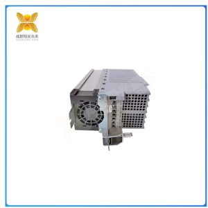
R911311065
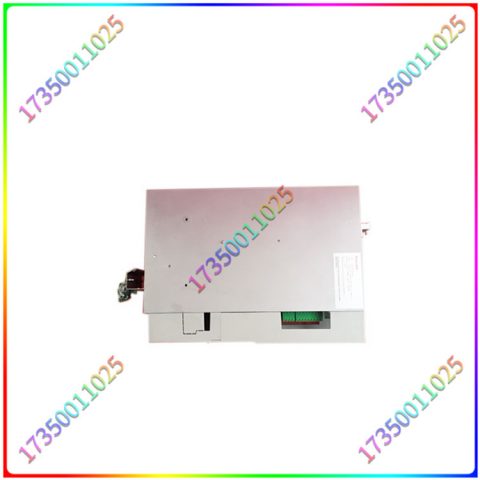
速度控制范围-0-400Hz。制动-至小130欧姆的外部电阻器(未提供)-请参阅下面链接的电阻器选项或使用本页上的“哪个电阻器”按钮。功能-2个模拟/数字输入、5个数字输入、1个模拟输出、2个继电器触点组、RS232、RS485。用于公共母线节能应用的直流母线端子。可通过“IndraWorks”软件和PC电缆从PC进行编程-请参阅下面的链接产品。输入电流-7.7。输入电压-380-480V三相-20%+10%,50/60Hz±5%。符合IEC/EN 55011 A类环境(工业)的EMC滤波器壁挂式清洁环境或隔间安装。额定环境温度为40°C。上方和下方的通风空间-100mm。侧面通风空间-0mm(驱动器可并排安装)输出时的热损失。通过后部(顶部和底部)的2个可拆卸散热器安装支架安装。每个支架1 x 5.5mm直径的孔。
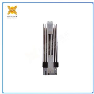
R911311065
High performance servo control: This drive module is designed to control servo motors, providing high-performance motion control, including precise positioning, speed control, and torque control. Multiple input/output interfaces: Typically, there are multiple input/output interfaces for connecting to different types of sensors, encoders, and other control devices. Multi axis control: This module typically supports multi axis control, allowing simultaneous control of multiple servo motors, making it suitable for multi axis motion applications. High resolution encoder feedback: Usually supports high-resolution encoders to provide high-precision position feedback. Open communication protocol support: Usually supports multiple open communication protocols, such as EtherCAT, CANopen, etc., to facilitate communication and integration with other control systems. Parameter adjustability: Users can usually adjust and configure parameters according to specific application requirements to achieve different motion control modes. Compact design: usually with a compact physical size, suitable for installation in limited spaces. Efficient and energy-saving: Advanced power electronic technology is often used to improve efficiency and reduce energy consumption.
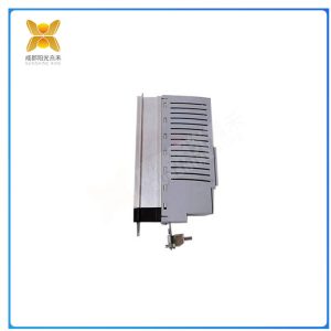
R911311065
The output circuit mainly sends signals to the outside through devices such as frequency converters or indicator lights during system operation. The design of the output circuit should start from the safety of the entire circuit. In the design process of the output circuit, it is necessary to follow the requirements of the PLC automation control system and use transistors to improve the system’s operational efficiency. In working environments with relatively low operating efficiency, it is possible to choose to use continuous current devices as output circuit devices. This workflow is relatively simple, and the corresponding work efficiency is also high, which can greatly enhance the load capacity of the output circuit of the PLC automation control system. If the PLC output carries some inductive loads, the load will cause surge current impact on the PLC output in the event of power outage. Measures such as connecting a diode next to the DC inductive load and AC inductive load with surge can be taken to absorb the circuit and protect the PLC
R911311065
Speed control range -0-400Hz. Braking – External resistor up to 130 ohms (not provided) – refer to the resistor options linked below or use the ‘Which resistor’ button on this page. Functionality -2 analog/digital inputs, 5 digital inputs, 1 analog output, 2 relay contact groups, RS232, RS485. DC bus terminals for energy-saving applications in public buses. Programming can be done from a PC through the “IndraWorks” software and PC cable – please refer to the linked product below. Input current -7.7. Input voltage -380-480V three-phase -20%+10%, 50/60Hz ± 5%. EMC filter wall mounted clean environment or compartment installation in accordance with IEC/EN 55011 Class A environment (industrial). The rated ambient temperature is 40 ° C. Ventilation space above and below -100mm. Heat loss during output when the side ventilation space is -0mm (drivers can be installed side by side). Install through 2 detachable radiator mounting brackets at the rear (top and bottom). Each bracket has 1 x 5.5mm diameter holes.


There are no reviews yet.